Automation in the manufacturing industry is being increasingly adopted at all levels of the production line and will be the norm in the very near future. It tremendously increases the efficiency and cost-effectiveness of processes where large amount of information has to be analysed manually in highly repetitive patterns and will soon replace human intervention even in tasks requiring high level reasoning. This article shows an example of how such kind of processes can negatively impact the production and how even simple low cost intelligent artificial vision systems can dramatically reduce the problem.
1. Introduction
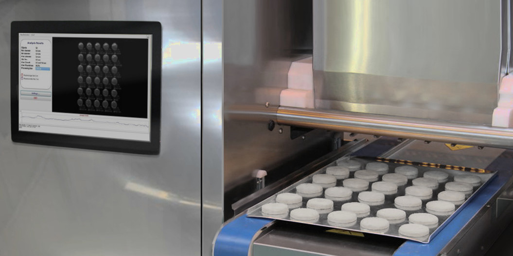
In 2012 I offered consultation services to an Australian business that manufactures macarons, a popular French confection very similar to a cookie. The main features of this confection are its rounded bulging shape,  dimension and colour. These features were manually inspected in the production line by human operators after the machine dropped the material on the tray and before entering the oven, in order to detect malformed units and remove them before being baked so that the material would not be wasted by producing macarons with a “funny” shape that could not be sold.
Also, it’s important that all the drops on a tray are of the same size in order to produce uniformly sized macarons when baked. Considering that a tray contained tens of macarons and that this process was repeated many times in a day, the manual inspection process was time consuming, and inefficient (humans are exceptionally good when focusing on a task but their performance drops quickly over time). The company wanted to free the workers from this manual process by introducing a system that could perform the same task automatically.
2. Design principles
The problem of automating the manual inspection of items in the production line for Quality Assurance is typical of the manufacturing industry and is often solved using artificial vision systems. Given the not complex morphology of the product (regular shape and size) the decision was made to implement a custom computer vision system that would replace the manual inspection process, which consisted in analysing each one of the tens of macarons on a tray arranged in a grid layout as they come out from the depositor and detecting those with a malformed shape and with sizes that are too small or too big.
This operation even when performed by a worker with a well trained eye may take several seconds and considering that it is repeated several times in a typical production day it will put considerable amount of fatigue on the operator resulting in quick decrease of performances and inefficiency (bottlenecked process). The aim of the computer vision system was that of replacing human intervention in the inspection phase by automatically detecting defects in a fraction of a second and signal the operator, through visual feedback, the bad macarons in order to be quickly removed from the tray. One of the requirements was to keep the overall cost within a limited budget, so the system had to account for this in its design on both the software and hardware side.
3. Components
The system comprises the following components:
- An industrial-grade camera
- A processing unit
- A software component implementing the computer vision logic
- A display for real-time feedback and reports
- A motion sensor to automatically trigger the analysis process
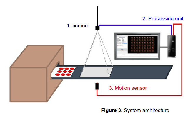
One of the decisions that an engineer faces when implementing a computer vision system is the choice of the most appropriate camera and its interface to the processing unit.
Regarding the resolution, one aspect to be considered was the size of the tray that had to fit within the field of view of the camera, which required it be positioned at a distance from the tray plane while at the same time the need to have enough resolution to compute sizes down to the millimeter. In regards to the speed, the application did not have hard real-time requirements, so there was not the need for a high-speed interface such as Firewire, Ethernet, etc. The camera used in the system was a CMOS Mightex USB 2.0 imager supporting a resolution of 3MP. The USB interface permitted the use of a pre-existent desktop computer board as the processing unit running a Windows OS (Windows 8).
The software has been designed with high modularization in mind using the principle of componentization in order  to achieve the highest level of decoupling. This was implemented using object oriented interfaces that clearly expose the functionality of each component regardless of internal details allowing easy interchangeability. The overall architecture follows a MVC pattern in order to separate the visualization concerns of the GUI from the processing logic and all the plumbing in between.
The core of the vision system is a software component implementing custom computer vision algorithms designed for this specific use case. These are based on a combination of clustering-driven segmentation and edge detection algorithms in order to detect the material drops on the tray, extract and analyse the features of interest such as shape, size, and other statistical parameters (more details in Appendix B). The algorithms have been developed in C++, using OpenCV for common image processing tasks, and encapsulated into a DLL exposing a pseudo-COM interface.
The GUI was developed using a RAD IDE (C++ Builder). In order to automate the triggering of the detection and analysis process, a sensor would detect the presence of the tray within the field of view of the camera, signalling the system (or the camera put in trigger mode) which in turn would send a grab event to the software initiating the  analysis process and displaying the results on a screen through the GUI.
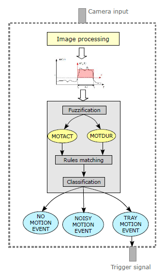
To minimize the number of components, the used approach was that of implementing a “software sensor” within the processing component itself using a motion detection algorithm. This solution, other than be more elegant, has spared us the use of an additional hardware component to be used as external motion sensor. The motion detection algorithm is based on the analysis of the energy flux within the field of view of the camera and a fuzzy classifier as a decision making tool of whether a tray has been moved in the FOV or not. A test of this sensor can be seen in this video . For more details see Appendix A.
One of the most challenging issues was the lighting in the environment. This is a common problem in many computer vision applications leading to segmentation errors and, consequently, to an increase of false negatives and/or positives caused by unwanted lighting effects. In our case, there was no additional artificial lighting provided, the only source being the pre-existent illumination and due to the nature of the material, light reflections on the drops and background was causing some troubles in the objects segmentation leading to some false negatives while shadowing affected the computation of the measures often introducing errors of -1/2 millimiters.
Fortunately, in industrial machine vision the environments are usually controlled (or can be made controllable) in order to create the most favourable lighting conditions, unlike in outdoor applications where it is hard to tightly control the different parameters that affect the vision system, especially lighting and shadowing. The problem could be solved by simply creating an artificial illumination to compensate all the issues arising by unwanted lighting effects. This will increase the accuracy up to close 100%.
Further improvements are still possible by, for example, adding a laser pointing system to indicate the bad macarons directly on the tray rather than on a screen in order to speed up their removal.
4. Conclusions
Tasks with repetitive patterns in the manufacturing processes can introduce inefficiency and bottlenecks when the amount of information to be analyzed manually is large (many features for many items at the same time). We’ve seen how such problems can be tackled even with low cost solutions to dramatically improve the process reducing bottlenecks.
Computer vision systems and robotics are definitely the solution to these problems and with the advance of technology and the advent of more intelligent machines it is not hard to see a future where automation will replace human intervention even for tasks requiring high level reasoning.
APPENDIX A
The software sensor for motion detection is based on the Energy Flux, which is defined as follows
$$ E_F(t)=\sum_{x \in I}[I_t^N(x) – I_{t-1}^N(x)]^2 \tag{1} $$
where
$$ I^N(x) = K_1I(x) – K_2 \hspace{20pt} K_1 = 1/\sigma, \hspace{10pt} K_2 = \mu/\sigma $$
\(I^N(x)\) being the normalized image. The normalized image is used as it is more robust to lighting changes and other illumination disturbances. To contrast spurious oscillations in the signal, hysteresis is applied before the integration process to the intensity values.
The energy flux is a good feature for detecting motion activities but it is not directly used as an input to the fuzzy classifier because the instantaneous value of (1) alone is not sufficient for robust discrimination. Adding information about the duration of the motion activities will increase the accuracy of the classification. When some motion is detected, that is (1) is greater than a threshold \(\tau\) (this is internally fixed by the algorithm for noise filtering), the energy flux is integrated over time according to the following
$$ EF_{\mu} = \frac{1}{\Delta T} \int_{0}^{\Delta T} E_F(t’)dt’ \tag{2} $$
where
$$ \Delta T = min(t’, T_{max}) \hspace{20pt} (3) \hspace{20pt} t’=t-t_a \hspace{10pt} t \geq t_a $$
\(T_{max}\) being the maximum possible motion event duration.

(2) and (3) will be the input variables to the fuzzy classifier. The decision of whether a motion activity is to be attributed to the tray moving into the field of view of the camera is made by a 2 input-3 output fuzzy classifier.
The cut points of the fuzzy sets are computed from the energy flux and motion activities readings taken experimentally on the field. We’re interested in detecting motion events inside the camera’s FOV that regard the positioning of the tray. Any other type of motion activity shall be regarded as “noise”. Considering that the environment has a good degree of controllability (we can act on most of the variables) a simple set of linguistic rules can be built to capture the knowledge about the process. The software sensor used in the system has the following architecture
APPENDIX B
The idea underlying the design and implementation of the computer vision algorithms follows the KISS philosophy. The use of sophisticated object detection techniques seemed a bit too overkill considering the low complexity of the operating context. The scene is pretty much static, the objects are not subject to any affine transformation and have features that can be deterministically estimated with simple formulae. Two algorithms have been implemented that can be selected by the user in the GUI: one based on edge-detectors and another one based on spectral segmentation.
The algorithm based on edge detection uses a combination of Canny detector, contour tracker and a set of geometric measures such as minor/major axis, roundness, area, etc. derived from geometrical operations on the contours (using moments of various orders or helper functions from OpenCV) and a rejection matrix to eliminate unwanted objects caused by noise.
The algorithm based on spectral segmentation uses a clustering method (k-means) in order to detect the objects of interest. In the first stage the frame image is low-pass filtered using a Gaussian kernel with aperture of 3 in order to eliminate noise and improve the processing in subsequent stages. Next comes the segmentation process. In our case we are interested in separating the material drops (usually only one colour) from the background and other foreign objects, so we use k=3, but this parameter may be set in the GUI to adapt to different scenarios. The clustering is performed in the HSV space using only the H and S components as this proved to give the best segmentation results.
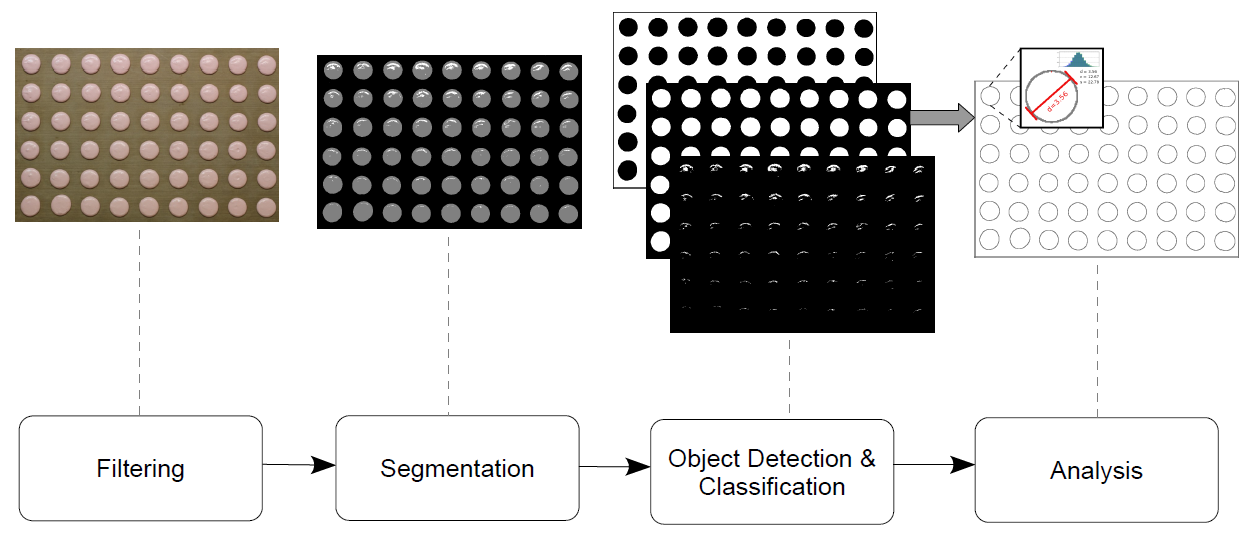
The results of the segmentation step is the separation of the objects of interest (the material drops) from the rest, such as background and other noise (mostly represented by lighting effects, especially reflections). The next step performs the object detection using contour finding in order to extract some geometric features. Finally, a classification can be done using these features and a-priori knowledge resulting in the final drops being recognized and ready for analysis. Given the size, shape, colour and regularity of the drops it is pretty easy to separate them from the background (big and holed) and from other noise (small and irregular).